The most common and widely used type of heat exchangers used in industry are shell and tube heat exchangers that are designed and manufactured for different applications and in different sizes. This type of heat exchanger is used to evaporate a liquid or condense a vapor or transfer heat between two liquids.
The components of a shell and tube heat exchanger are: tube, tube sheet, shell, front end, rear end and retaining plates (Baffles). Shell and tube heat exchangers consist of a large number of tubes containing fluid, the outer part of which is in contact with another fluid, and the heat transfer operation is possible through the interface surface, which is the body or wall of the tube. Therefore, the material of the pipes should be chosen in such a way that in addition to endurance, they are also good conductors of heat. In shell and tube heat exchangers, usually two metal plates are placed at the beginning and end of the heat exchanger, which is punctured on the number of tubes inside the heat exchanger, and these tubes are welded to the tube sheet or by means of mechanically connected.
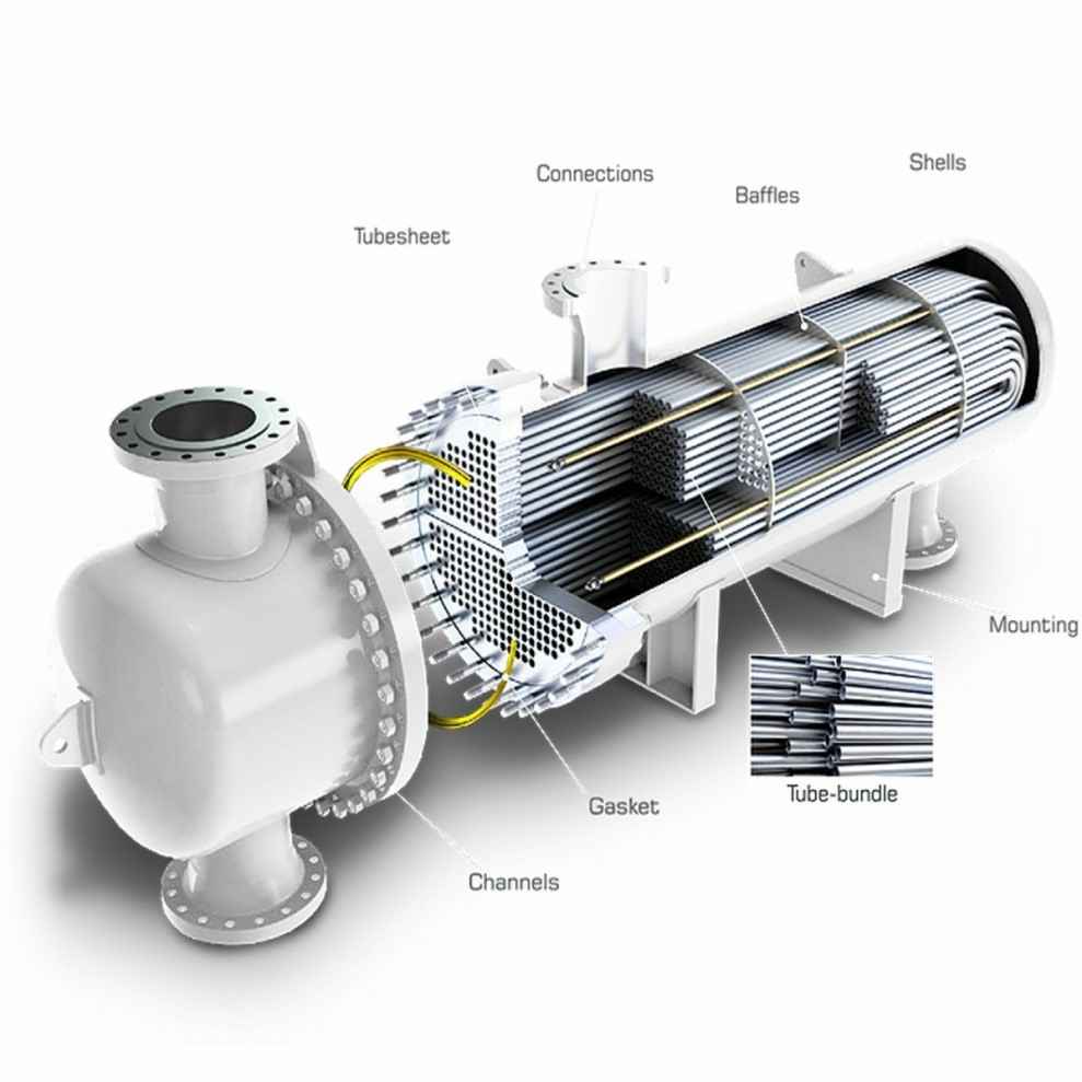
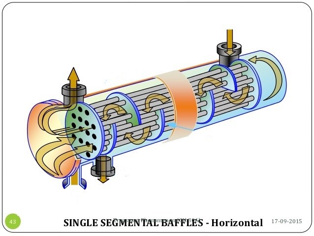
The fluid that passes through the shell must be directed in such a way that it makes the most contact with the outer surface of the pipes along the way and the heat transfer process takes place in the best way. To achieve this, a piece called a baffle is used. Baffles are used in converters for two purposes. Conduct fluid and hold pipes to prevent vibration and displacement. By installing the baffles, the flow of fluid in the shell is almost perpendicular to the flow of fluid inside the pipes, which increases the heat transfer and thus increases the work efficiency.
TEMA Designations
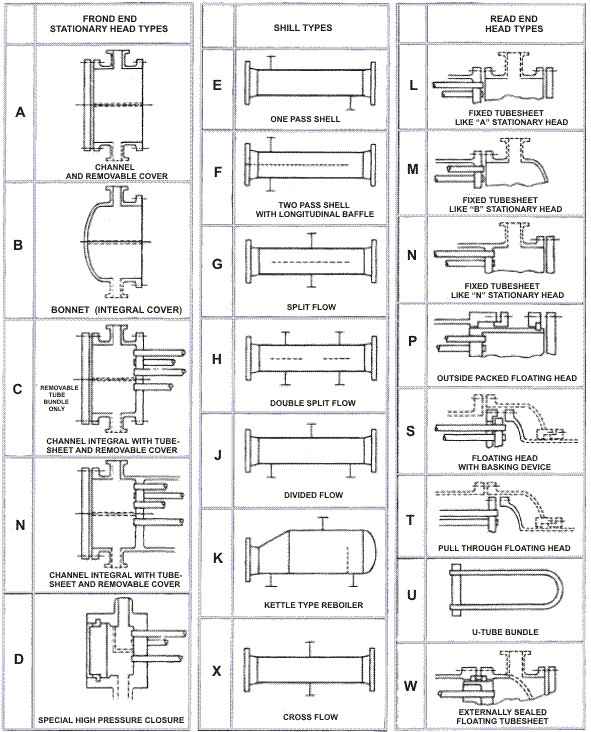
The popularity of shell and tube exchangers has resulted in a standard nomenclature being developed for their designation and use by the Tubular Exchanger Manufactures Association (TEMA). This nomenclature is defined in terms letters and diagrams. The first letter describes the front header type, the second letter the shell type and the third letter the rear header type. The figure below shows how to name it, which is explained in full below.
Essentially there are three main combinations
- Fixed tubesheet exchangers
- U-tube exchangers
- Floating header exchangers
Fixed Tubesheet Exchanger (L, M, and N Type Rear Headers)
In a fixed tubesheet exchanger, the tubesheet is welded to the shell. This results in a simple and economical construction and the tube bores can be cleaned mechanically or chemically. However, the outside surfaces of the tubes are inaccessible except to chemical cleaning.
If large temperature differences exist between the shell and tube materials, it may be necessary to incorporate an expansion bellows in the shell, to eliminate excessive stresses caused by expansion. Such bellows are often a source of weakness and failure in operation. In circumstances where the consequences of failure are particularly grave U-Tube or Floating Header units are normally used.
This is the cheapest of all removable bundle designs, but is generally slightly more expensive than a fixed tubesheet design at low pressures.
U-Tube Exchangers
In a U-Tube exchanger any of the front header types may be used and the rear header is normally a M-Type. The U-tubes permit unlimited thermal expansion, the tube bundle can be removed for cleaning and small bundle to shell clearances can be achieved. However, since internal cleaning of the tubes by mechanical means is difficult, it is normal only to use this type where the tube side fluids are clean.
Floating Head Exchanger (P, S, T and W Type Rear Headers)
In this type of exchanger the tubesheet at the Rear Header end is not welded to the shell but allowed to move or float. The tubesheet at the Front Header (tube side fluid inlet end) is of a larger diameter than the shell and is sealed in a similar manner to that used in the fixed tubesheet design. The tubesheet at the rear header end of the shell is of slightly smaller diameter than the shell, allowing the bundle to be pulled through the shell. The use of a floating head means that thermal expansion can be allowed for and the tube bundle can be removed for cleaning. There are several rear header types that can be used but the S-Type Rear Head is the most popular. A floating head exchanger is suitable for the rigorous duties associated with high temperatures and pressures but is more expensive (typically of order of 25% for carbon steel construction) than the equivalent fixed tubesheet exchanger.
Considering each header and shell type in turn:
A-Type front header
This type of header is easy to repair and replace. It also gives access to the tubes for cleaning or repair without having to disturb the pipe work. It does however have two seals (one between the tube sheet and header and the other between the header and the end plate). This increases the risk of leakage and the cost of the header over a B-Type Front Header.
B-Type front header
This is the cheapest type of front header. It also is more suitable than the A-Type Front Header for high pressure duties because the header has only one seal. A disadvantage is that to gain access to the tubes requires disturbance to the pipe work in order to remove the header.
C-Type front header
This type of header is for high pressure applications (>100 bar). It does allow access to the tube without disturbing the pipe work but is difficult to repair and replace because the tube bundle is an integral part of the header.
D-Type front header
This is the most expensive type of front header. It is for very high pressures (> 150 bar). It does allow access to the tubes without disturbing the pipe work but is difficult to repair and replace because the tube bundle is an integral part of the header.
N-Type front header
The advantage of this type of header is that the tubes can be accessed without disturbing the pipe work and it is cheaper than an A-Type Front Header. However, they are difficult to maintain and replace as the header and tube sheet are an integral part of the shell.
Y-Type front header
Strictly speaking this is not a TEMA designated type but is generally recognized. It can be used as a front or rear header and is used when the exchanger is to be used in a pipe line. It is cheaper than other types of headers as it reduces piping costs. It is mainly used with single tube pass units although with suitable partitioning any odd number of passes can be allowed.
E-Type shell
This is most commonly used shell type, suitable for most duties and applications. Other shell types only tend to be used for special duties or applications.
F-Type shell
This is generally used when pure countercurrent flow is required in a two tube side pass unit. This is achieved by having two shells side passes—the two passes being separated by a longitudinal baffle. The main problem with this type of unit is thermal and hydraulic leakage across this longitudinal baffle unless special precautions are taken.
G-Type shell
This is used for horizontal thermosyphon reboilers and applications where the shellside pressure drop needs to be kept small. This is achieved by splitting the shellside flow.
H-Type shell
This is used for similar applications to G-Type Shell but tends to be used when larger units are required.
J-Type shell
This tends to be used when the maximum allowable pressure drop is exceeded in an E-Type Shell even when double segmental baffles are used. It is also used when tube vibration is a problem. The divided flow on the shellside reduces the flow velocities over the tubes and hence reduces the pressure drop and the likelihood of tube vibration. When there are two inlet nozzles and one outlet nozzle this is sometimes referred to as an I-Type Shell.
K-Type shell
This tends to be used when the maximum allowable pressure drop is exceeded in an E-Type Shell even when double segmental baffles are used. It is also used when tube vibration is a problem. The divided flow on the shellside reduces the flow velocities over the tubes and hence reduces the pressure drop and the likelihood of tube vibration. When there are two inlet nozzles and one outlet nozzle this is sometimes referred to as an I-Type Shell.
X-Type shell
This is used if the maximum shellside pressure drop is exceeded by all other shell and baffle type combinations. The main applications are shellside condensers and gas coolers.
L-Type rear header
This type of header is for use with fixed tubesheets only, since the tubesheet is welded to the shell and access to the outside of the tubes is not possible. The main advantages of this type of header are that access can be gained to the inside of the tubes without having to remove any pipework and the bundle to shell clearances are small. The main disadvantage is that a bellows or an expansion roll are required to allow for large thermal expansions and this limits the permitted operating temperature and pressure.
M-Type rear header
This type of header is similar to the L-Type Rear Header but it is slightly cheaper. However, the header has to be removed to gain access to the inside of the tubes. Again, special measures have to be taken to cope with large thermal expansions and this limits the permitted operating temperature and pressure.
N-Type rear header
The advantage of this type of header is that the tubes can be accessed without disturbing the pipe work. However, they are difficult to maintain and replace since the header and tube sheet are an integral part of the shell.
P-Type rear header
This is an outside packed floating rear header. It is, in theory, a low cost floating head design which allows access to the inside of the tubes for cleaning and also allows the bundle to be removed for cleaning. The main problems with this type of header are:
• large bundle to shell clearances required in order to pull the bundle;
• it is limited to low pressure nonhazardous fluids, because it is possible for the shellside fluid to leak via the packing rings;
• only small thermal expansions are permitted.
In practice it is not a low cost design, because the shell has to be rolled to small tolerances for the packing to be effective.
S-Type rear header
This is a floating rear header with backing device. It is the most expensive of the floating head types but does allow the bundle to be removed and unlimited thermal expansion is possible. It also has smaller shell to bundle clearances than the other floating head types. However, it is difficult to dismantle for bundle pulling and the shell diameter and bundle to shell clearances are larger than for fixed head type exchangers.
T-Type rear header
This is a pull through floating head. It is cheaper and easier to remove the bundle than with the S-Type Rear Header, but still allows for unlimited thermal expansion. It does, however, have the largest bundle to shell clearance of all the floating head types and is more expensive than fixed header and U-tube types.
U-tube
This is the cheapest of all removable bundle designs, but is generally slightly more expensive than a fixed tubesheet design at low pressures. However, it permits unlimited thermal expansion, allows the bundle to be removed to clean the outside of the tubes, has the tightest bundle to shell clearances and is the simplest design. A disadvantage of the U-tube design is that it cannot normally have pure counterflow unless an F-Type Shell is used. Also, U-tube designs are limited to even numbers of tube passes.
W-Type rear header
This is a packed floating tubesheet with lantern ring. It is the cheapest of the floating head designs, allows for unlimited thermal expansion and allows the tube bundle to be removed for cleaning. The main problems with this type of head are:
• the large bundle to shell clearances required to pull the bundle and;
• the limitation to low pressure nonhazardous fluids (because it is possible for both the fluids to leak via the packing rings).
It is also possible for the shell and tube side fluids to become mixed if leakage occurs.